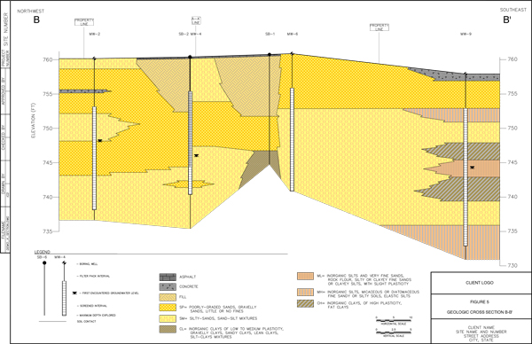
Geologic Cross Sections
A typical Geologic Cross Section / Fence Diagram includes up to 7 wells/soil borings, with or without survey data, excluding any soil or groundwater analytical data.
Along with the geologic cross section request, the following information is needed:
- Site Map including geologic cross section line(s), preferrably in AutoCAD format
- Boring Logs (in PDF format)
- Monitoring well Top of Casing (TOC) and soil boring ground surface elevation data, if you require depicting changes in surface elevation along the cross section.
We can draft geologic cross sections according to the provided data (see above), according to a sketch provided by the client, depicting all the soil layers, or as a ‘sticks-only’ figure – including soil boring, monitoring well construction data and soil type interfaces, marked on the borings and wells, allowing client to fill in the geologic layer interfaces between borings. We also draft Conceptual Site Models, Boring Logs, and other figures for environmental consulting and geotechnical engineering industries.
All figure requests are made in our cloud-based work management system on a fixed-price basis, and figures are completed within 7 days.